Overview of the drainage network: In line with the sponge city concept, this road is designed as a low-impact stormwater system. It utilizes a sunken green belt, prioritizing rainwater within the road's red line to be channeled into the sunken green spaces on both sides for infiltration, filtration, retention, and storage. An overflow inlet is installed in the center of the green belt, and a stormwater pipe is installed under the non-motorized vehicle lane. Rainwater from the sunken green space is discharged through the overflow inlet into the stormwater pipe. A water barrier imitating wooden piles is installed 5 meters downstream of the stormwater inlet.
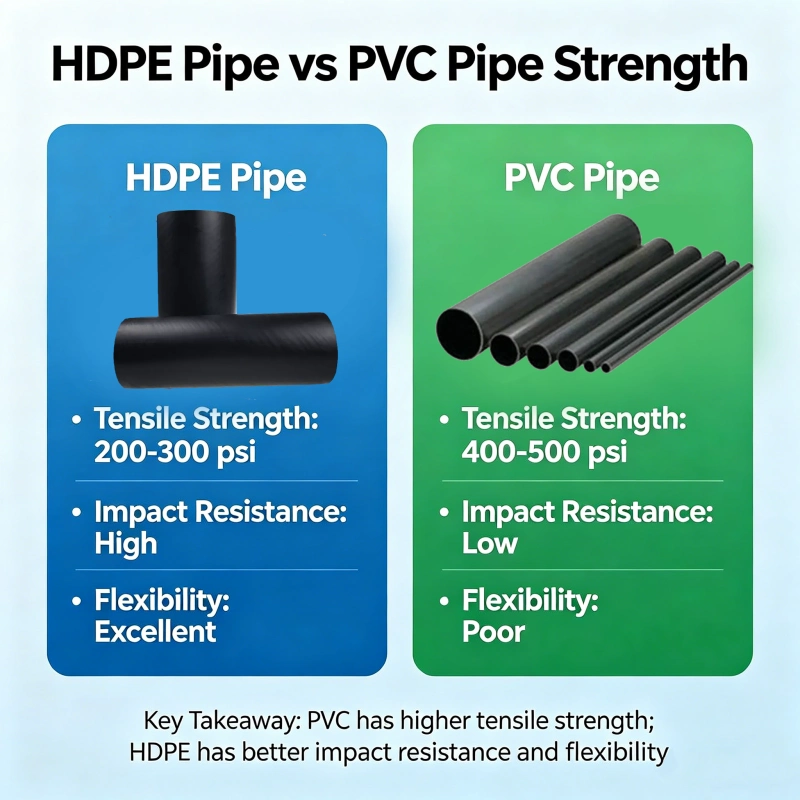
Curbstones are opened every 15 meters, located downstream of the stormwater inlet to prevent water accumulation at the lowest point. The planting soil in the side strip is 1.5 meters thick. To increase permeability, 20% fine sand is incorporated into the planting soil. A De200 longitudinal perforated drainage pipe with a porosity of 1% to 3% is installed at the bottom of the planting soil, connecting to the overflow stormwater inlet. The perforated drainage pipe is wrapped with a 0.5-meter-wide and 0.3-meter-deep gravel layer with a maximum particle size of 3 cm and a mud content of no more than 1%. The gravel layer is wrapped with a permeable geotextile. For sewage pipes with a diameter of d ≤ 500,
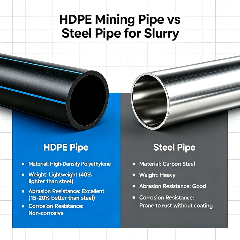
HDPE pipe is used with a ring stiffness of no less than 12.5 kN/m2. A gravel foundation is used for the pipe foundation. For sewage pipes with a diameter greater than 500, jacking reinforced concrete pipe (Grade III) is used for deeper installation. For shallower installations, trenching is used, following the same installation requirements as for rainwater pipes. The connection between the rainwater pipe and the rainwater outlet adopts reinforced concrete pipe (grade II), rubber ring interface, and the pipe foundation adopts gravel foundation.
Drainage network construction technology
Survey construction process: Control pile handover → Control pile re-survey → Control network densification → Original landform measurement → Excavation construction measurement → Pipeline foundation construction measurement → Pipeline and well chamber construction measurement → Backfill construction measurement → Completion measurement
Plane position measurement
(1) The vertical and horizontal axes and well positions required for pipe network construction are measured according to the internal calculation data using plane control points. The starting point, end point, plane inflection point and straight line control point of the pipeline centerline are measured. The polar coordinate method is used to directly lay out the center stakes using a total station. The center stakes are nailed on the top of the stakes, and the pile guards are prepared so that the pile position deviation can be checked at any time.
(2) After the trench is formed, the center line is projected to the bottom of the trench in time using a total station and the center stakes are nailed. Each supply and return pipeline should be set with a center stake and marked separately.
Pipeline elevation control
(1) Two elevation control points form a ring for temporary leveling point survey and calibration. Temporary leveling points are placed in a stable and untouchable place with a distance of no more than 100m between them and should be re-measured frequently; two temporary leveling points form a ring for construction elevation point survey and calibration. Construction elevation points should be re-measured before each use.
(2) When controlling the trench bottom and laying the pipeline, a pair of elevation control piles are measured and set every 10m on both sides of the trench using construction elevation points. The pile numbers are marked, and elevation nails are nailed and painted with red paint marks as auxiliary elevation control.
Trench excavation measurement:
(1) Before trench excavation, the center line is located according to the design and construction plan. When the "polar coordinate method" is used to measure and lay the pipeline center line, center piles are measured and set at the starting point, end point, plane inflection point, vertical inflection point and control point of the straight line segment.
(2) After the trench bottom is inspected, the pipeline centerline control pile is projected to the trench bottom using the theodolite projection method based on the positioning control pile, and the ground elevation is guided to the trench bottom using a level.
Process name: Pipeline foundation measurement
Measure and lay out the pipeline foundation structure width based on the pipeline center pile and the designed foundation width after the bottom inspection, and at the same time measure and lay out the pipeline foundation elevation control pile. After the foundation construction, re-measure the foundation centerline deviation, width and elevation.
Trench excavation construction
Manual excavation with mechanical excavation
The proposed excavation construction shall all be carried out by manual excavation with mechanical excavation. When excavating the pipeline trench, the excavation sequence, route and excavation depth shall be reasonably determined; then, the excavation shall be carried out evenly in sections and layers. During excavation, the excavation depth shall be measured and tracked. Before the trench bottom is formed, plates or slope piles shall be buried in time and the trench centerline and elevation shall be marked.
Slope excavation
Before the pipeline trench is excavated, the trench centerline shall be measured and the ground elevation shall be re-measured. The trench excavation shall adopt the slope excavation method.
Support Excavation
When slope excavation is not feasible due to environmental and soil conditions, a feasible slope support scheme must be implemented. During excavation, comprehensive consideration should be given to the support structure type, ensuring support before excavation or excavation while supporting. For support before excavation, excavation should generally not proceed until the support structure strength reaches at least 70% of the design strength.
Trench Drainage
During trench excavation, drainage ditches measuring 300×300mm are installed outside the working surface on both sides of the trench bottom. Sumps measuring 1000×1000×500mm are installed every 50 meters along the trench. Before trench backfilling, submersible pumps are used to pump water out of the pits to ensure no water accumulates in the trench during construction.
Inspecting the Trench Bottom
After trench excavation is complete, inspect the trench bottom as soon as possible. Then, backfill with stone or construct a concrete foundation. If the foundation soil is poor, excavate to the original soil layer, backfill with crushed stone to the trench bottom elevation, and compact it before preparing for pipe laying or concrete foundation construction. After foundation construction is completed, inspect the area between two wells, with one inspection point every 10 meters, with a minimum of three inspection points.
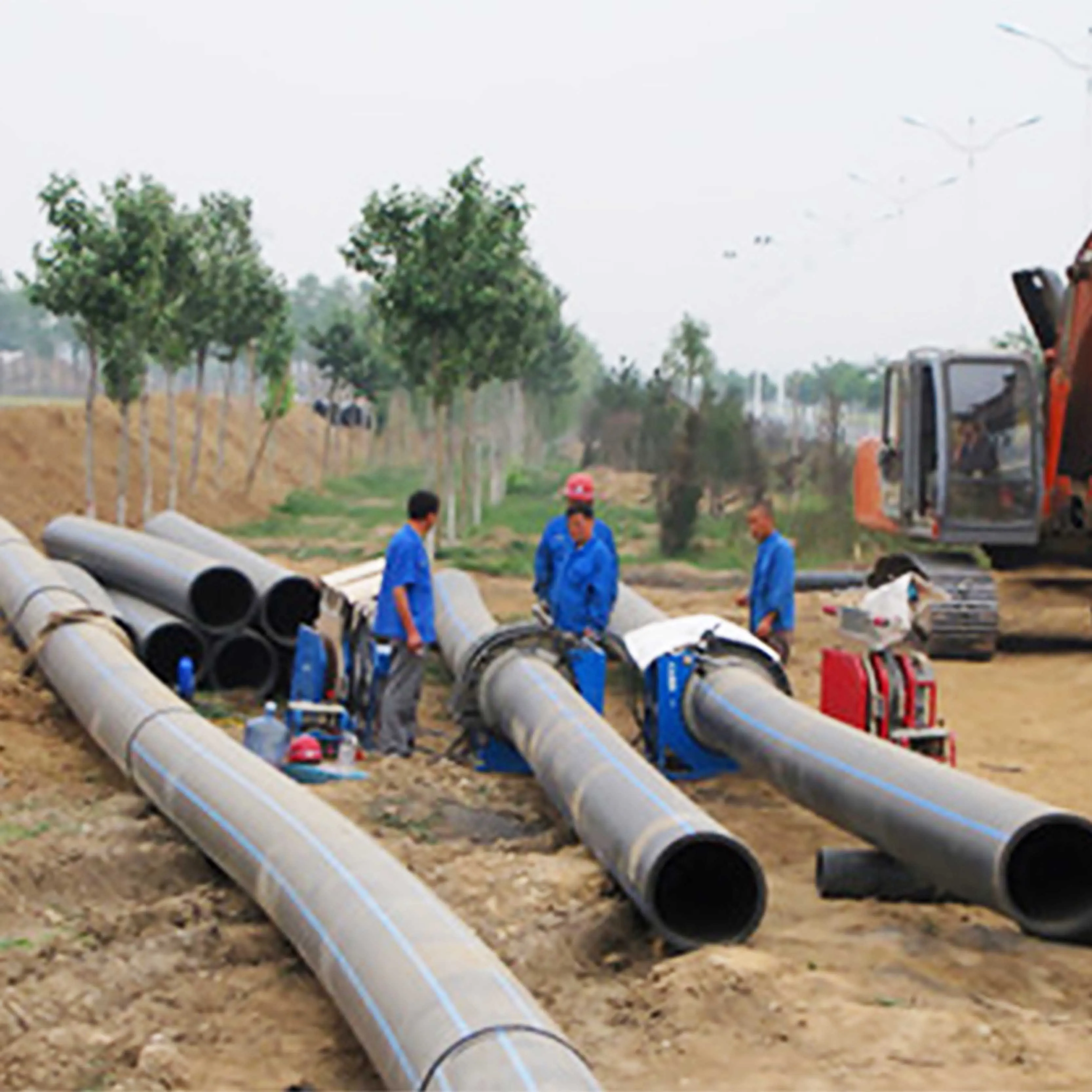
HDPE Pipe Installation
Trench Cleaning and Laying Out
Before laying pipes, remove debris from the pit, reinforce the foundation pit support, and drain any accumulated water. Then, mark the pipe centerline on a flat foundation and verify the flat foundation elevation.
Pipe Laying
Depending on the pipe diameter and site conditions, a combination of manual and crane lowering may be used. When laying pipes, arrange the pipes properly and align them. Strictly control the centerline and elevation. Lay pipes from downstream to upstream, with the joints facing upstream. Each section of culvert should be flush against the cushion or foundation. Joint Preparation
Pipe joints should use spigot-and-socket joints with elastic sealing rubber rings. For pipes DN400 and smaller, one person should first hold the spigot of the pipe being installed with a cotton rope. Another person should insert a long crowbar diagonally into the foundation, resting against the horizontal baffle at the center of the pipe end. Then, forcefully insert the pipe into the spigot of the pipe to be installed until it reaches the desired position. For pipes DN400 and larger, two lever hoists can be used to pull the pipe joint into place. When closing the joint, the lever hoists on both sides of the pipe joint should be pulled simultaneously to ensure that the rubber sealing ring is properly seated and does not twist or fall off.
Rechecking the Flow Level
After the pipeline has stabilized, the flow level should be rechecked to ensure that the longitudinal slope meets the design requirements before proceeding to the next construction step.
Clean Debris
After the pipeline is laid, debris must be removed from the pipe.
Inspection Well Construction and Backfill
After the pipeline installation has passed the supervisor's inspection, the central inspection well will be constructed simultaneously. Backfill sand should be applied simultaneously and symmetrically on both sides of the pipe cavity to meet the required compaction level.
Installation of reinforced concrete pipes
Reinforced concrete pipe laying
(1) Before installing the pipe joint, an appearance inspection should be carried out to check the appearance of the pipe body and the size of the pipe body's socket and spigot, as well as the flatness of the working surface of the socket and spigot. Use a special diameter gauge to measure and record the inner diameter of the socket, outer diameter of the spigot and its ovality of each pipe. The circumferential clearance of the socket and spigot should meet the requirements of the selected rubber ring.
(2) Use a special high-strength nylon lifting belt to lower the pipe to avoid damaging the concrete of the pipe body. Before lifting, the center of gravity of the pipe body should be found and marked to meet the lifting requirements of the pipe body. When lowering the pipe, the socket of the pipe joint should face the direction of water flow. The pipe foundation should not be disturbed when lowering and installing the pipe.
(3) After the pipe is in place, two sets of four wedge-shaped concrete pads should be added on both sides of the pipe to prevent the pipe from rolling.
Clean the socket and spigot
(1) Before connecting the pipes, place the two connecting pipes on the same horizontal surface and wipe the pipe socket and spigot clean with a rag.
(2) Apply potassium salt grease soap solution to the socket.
Inspecting the rubber ring
(1) Check the specifications, models and quality of the rubber ring to see if they meet the design requirements.
(2) Conduct on-site inspections of the grade, nominal hardness, tensile strength, elongation at break, compression set, water resistance, etc. of the rubber ring to meet the construction requirements.
Installing the rubber ring
(1) Manually insert the clean rubber ring into the socket end and slowly wedge it into the pipe.
(2) Check that the outer edge of the rubber ring does not turn over (referring to the wedge-shaped rubber ring), twist it, and the rubber ring does not exceed the rubber stop. The installation position must be correct.
Inserting into the socket
(1) During the wedging process of the pipe, pay special attention to the balanced entry of the rubber ring.
(2) For the reinforced concrete pipes installed in this project, someone must enter the pipe to check the rubber ring to see if it is in the correct position. For small-diameter pipes that cannot be entered by people, the rubber ring must be monitored from the outside to prevent the rubber ring from being partially exposed, which is a location prone to installation quality accidents.
Cement mortar tape
(1) When applying the tape, fill the gaps in the pipe joints outside the rubber ring, fill the mortar in the pipe joints and tamp it firmly, then apply it in layers. (2) After applying, cover and water the tape to prevent hollowing and cracking.
214958.webp)
916.webp)
204.webp)
659.webp)
185.webp)
312.webp)
849.webp)
587.webp)
767.webp)