111.webp)
What are the requirements for pipeline layout design?
1. General requirements
1) The pipeline layout design must comply with the requirements of the process pipeline and instrument flow chart.
2) The pipeline layout should be planned in a comprehensive manner to ensure safety, reliability, economic rationality, meet the needs of construction, operation, maintenance, etc., and be as neat and beautiful as possible.
3) When determining the orientation and laying method of the pipelines entering and exiting the device (unit), internal and external coordination should be ensured.
4) The laying of the plant-wide pipelines in the factory area should be coordinated with the devices (units), roads, buildings, etc. in the factory area to prevent the pipelines from surrounding the devices (units) and reduce the intersection of pipelines with railways and roads.
5) The pipeline should be laid overhead or on the ground. If it is really necessary, it can be buried or laid in a trench.
6) It is best to arrange the pipelines in rows, and the pipelines on the ground should be laid on pipe racks or pipe piers.
7) When arranging pipelines on pipe racks and pipe piers, the vertical load and horizontal load borne by the pipe racks or pipe piers should be balanced.
8) A 10%-30% margin should be reserved on the plant-wide pipe rack or pipe pier (including crossing culverts), and its load should be considered; it is best to reserve a 10%-20% margin on the pipe rack of the main corridor of the device, and its load should be considered.
2. Pipes connected to equipment
9) The layout of pipelines with special requirements for distance, angle, height difference, etc. for the conveying medium and large-diameter pipelines should meet the requirements of equipment layout design;
10) The pipeline layout should not hinder the installation, maintenance and passage of equipment, pumps and their internal components;
11) The pipeline layout should make the pipeline system have the necessary flexibility. While ensuring the flexibility of the pipeline and the force and torque of the pipeline on the equipment and pump nozzles do not exceed the allowable value, the pipeline should be as short as possible and the components should be the least;
12) The setting of its support points should be considered while planning the pipeline. It is advisable to use the natural shape of the pipeline to achieve self-compensation;
3. Considered process factors
13) The pipeline layout should be "step by step" or "step by step" to reduce air bags or liquid bags. When it is unavoidable, venting and cleaning should be set up according to the requirements of operation and maintenance, and the pipeline layout should reduce "blind intestines";
14) When the pipeline of gas-liquid two-phase flow is divided from one to two or more, the pipeline layout should consider symmetry or meet the requirements of pipeline and instrument flow chart.
15) Except for those that need flange or thread connection with valves, instruments, equipment, etc., the pipeline should be connected by welding. Flange, thread or other detachable connection should be considered in the following situations: occasions where disassembly is required for maintenance, cleaning, and purging; lined pipes or jacketed pipes; pipes composed of two sections of dissimilar materials and not suitable for welding connection; pipe connection points where it is difficult to heat treat the weld on site; galvanized pipes with a nominal diameter less than or equal to 100mm; locations where blind plates or "8" blind plates are set.
16) Gas branch pipes should be connected from the top of the main pipe.
17) Toxic medium pipelines should be connected by welding, and flange or thread connection shall not be used unless there is a special need. Toxic medium pipelines should be clearly marked to distinguish them from other pipelines, and toxic medium pipelines should not be buried.
18) When arranging pipelines for solid materials or pipelines containing solid materials, the pipelines should be as short as possible. Fewer bends and no dead corners: The connection between the solid material branch pipe and the main pipe should be beveled along the flow direction of the medium, and the angle should not be greater than 45°; the bending radius of the elbow on the solid material pipeline should not be less than 6 times the nominal diameter of the pipeline; slurry pipelines containing a large amount of solid materials and high-viscosity liquid pipelines should have a slope.
4. Requirements for pipeline flexibility
19) For pipelines that require thermal compensation, the entire pipeline system should be analyzed from the starting point to the end point of the pipeline to determine a reasonable thermal compensation solution.
20) For pipelines that require a slope when laid on the pipeline corridor, the height of the pipe support can be adjusted. This can be achieved by adding steel or steel plate pillows to the pipe support. The venting gas main pipe (or flare main pipe) should be arranged at the top of the corridor column to facilitate the adjustment of the elevation.
21) When arranging pipelines connected to rotating mechanical equipment, the pipeline system should have sufficient flexibility to meet the allowable force requirements of the equipment pipe mouth. If necessary, the following measures can be adopted: change the direction of the pipeline to enhance the natural compensation capacity; use spring supports and hangers; use metal corrugated Corrugated pipe compensator; set limit brackets at appropriate locations.
5. Anti-vibration design of pipelines
22) When arranging pipelines connected to reciprocating compressors, the mechanical vibration natural frequency of the pipeline system and the natural frequency of the air column of the pipeline should be kept away from the excitation frequency of the machine. If necessary, the following measures can be adopted: add anti-vibration brackets; appropriately expand the pipe diameter; add pulsation attenuators or orifice plates; reasonably set buffers to avoid resonant pipe lengths and reduce elbows as much as possible.
23) Branch pipes should not be set at locations with large bending moments on vibrating pipelines.
24) At the bends of pipelines that are prone to vibration (such as reciprocating compressors, reciprocating pump outlet pipes, etc.), elbows with a bending radius of not less than 1.5 times the nominal diameter should be used. The branch pipe is connected to the outside in the direction of medium flow.
25) When a branch pipe with a nominal diameter less than or equal to 40mm is connected from a pipe that may vibrate, whether there is a valve on the branch pipe or not, reinforcement measures should be taken at the connection.
6. Pipeline layout under specific circumstances
26) The horizontal pipeline of gravity flow should have a slope of not less than 3‰ in the direction of medium flow.
27) When the pipeline passes through the floor, roof or wall of the building, a sleeve should be added, and the gap between the sleeve and the pipe door should be sealed. The diameter of the sleeve should be larger than the outer diameter of the pipe insulation layer and should not affect the thermal displacement of the pipe. The weld on the pipe should not be inside the sleeve and should not be less than 150mm from the end of the sleeve. The sleeve should be 50mm higher than the floor and roof surface. Pipe When the pipeline passes through the roof, a rain cover should be installed, and the pipeline should not pass through the firewall or explosion-proof wall.
28) When arranging corrosive media, toxic media and high-pressure pipelines, hazards to personnel and equipment caused by leakage of flanges, threads and packing seals should be avoided. Leakage-prone parts should not be located above pedestrian walkways or pumps, otherwise safety protection should be provided.
29) For pipelines with insulation layers, pipe supports should be installed at pipe piers and pipe racks. For pipelines without insulation layers, pipe supports may not be installed if there is no requirement. When the thickness of the insulation layer is less than or equal to 80mm, a 100mm high pipe support should be selected; when the thickness of the insulation layer is greater than 80mm, a 150mm high pipe support should be selected; when the thickness of the insulation layer is greater than 130mm, a 200mm high pipe support should be selected. mm pipe supports; cold-insulated pipe supports should be used for cold-insulated pipes.
30) When the plant area has a large elevation difference, the pipeline laying of the entire plant should be consistent with the terrain elevation difference. Adjust the elevation of the pipe gallery at an appropriate location. The minimum slope of the pipeline should be 2‰. The slope change point of the pipeline should be located near the turning point or the fixed point.
31) For pipelines that cross or pass through railways and roads within the plant area, valves, metal bellows compensators, flanges, threaded joints and other pipeline components shall not be installed on the crossing section or the crossing section.
32) For buried pipelines with thermal displacement, retaining piers can be set under the condition that the curvature of the pipeline allows, otherwise thermal compensation measures should be taken.
33) The setting of pipeline welds during pipeline layout shall meet the following requirements: The distance between the center of the pipeline butt weld and the bending point of the elbow shall not be less than the outer diameter of the pipe: and shall not be less than 100mm;
The center distance between two adjacent butt welds on the pipeline: a. For pipelines with a nominal diameter less than 150mm, it shall not be less than the outer diameter, and shall not be less than 50mm; b. For pipelines with a nominal diameter equal to or greater than 150m, it shall not be less than 150mm;
The net distance between the circumferential weld and the edge of the support and hanger shall not be less than 50mm; The minimum net distance between the weld that requires heat treatment and the edge of the support and hanger shall be greater than 5 times the weld width, and shall not be less than 100mm.
7. Pipeline layout with gas-liquid two-phase flow
34) Pipelines should be laid vertically first and then horizontally according to the flow direction of the medium, and should be short and straight;
35) The regulating valve on the pipeline should be arranged as close as possible to the container receiving the medium. If conditions permit, the regulating valve should be directly connected to the container receiving the medium;
36) The first turning elbow after the regulating valve should be replaced with a tee connection, and a plug should be added to one end of the tee straight connection;
37) Limits or fixed supports should be set at appropriate positions of the pipe system.
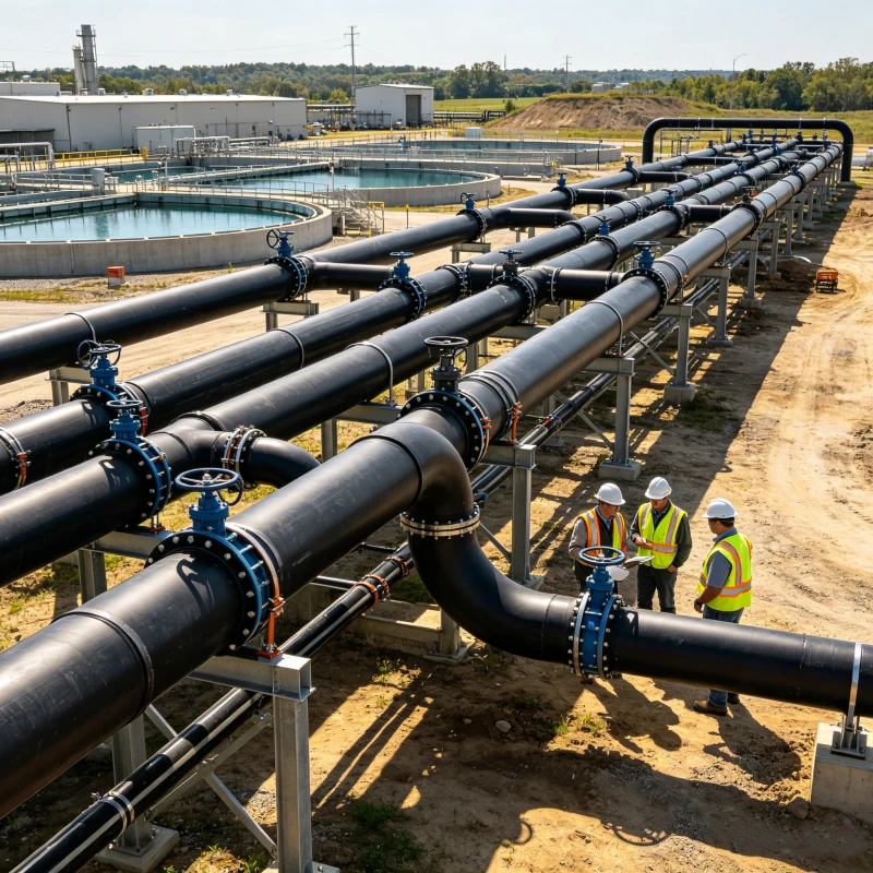
Pipe System: Foundation of Modern Infrastructure
A pipe system is a critical component of modern infrastructure, enabling the efficient transportation of liquids, gases, and even solids across various industries. Whether it’s supplying water to homes, transporting oil and gas across continents, or delivering essential chemicals in manufacturing plants, pipe systems play a vital role in sustaining industrial and domestic needs.
Importance of Pipe Systems
The versatility of pipe systems allows them to adapt to numerous applications:
1. Water Supply and Distribution: Pipe systems provide clean drinking water to urban and rural areas, ensuring public health and sanitation.
2. Wastewater Management: Sewer systems transport wastewater to treatment plants, reducing pollution and protecting the environment.
3. Industrial Applications: In factories, pipe systems carry steam, chemicals, and compressed air to support production processes.
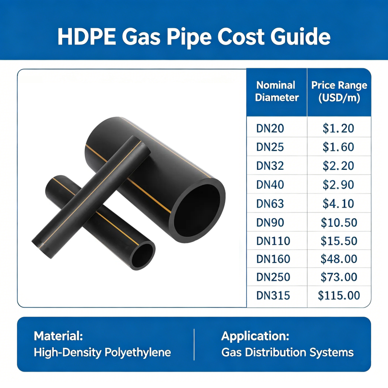
4. Energy Transportation: Oil and gas pipelines are lifelines for global energy distribution, connecting resources with markets.
Components of a Pipe System
A typical pipe system comprises various interconnected elements, each serving a specific function:
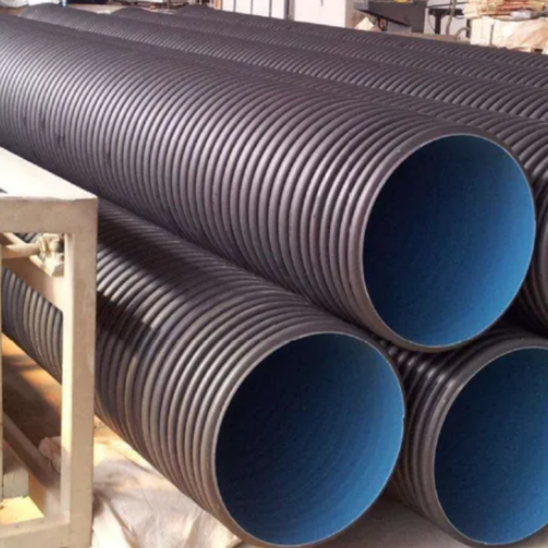
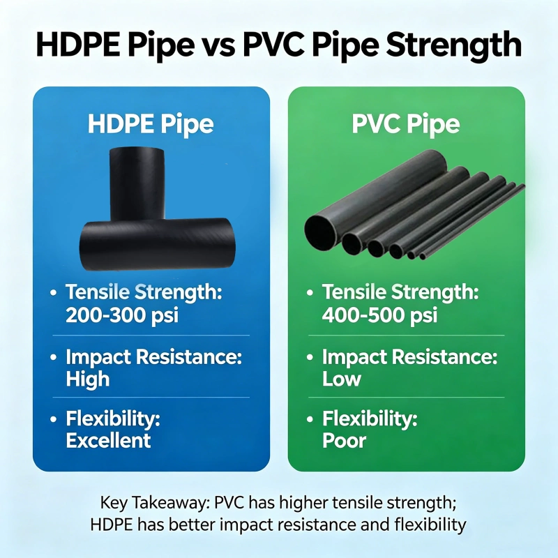
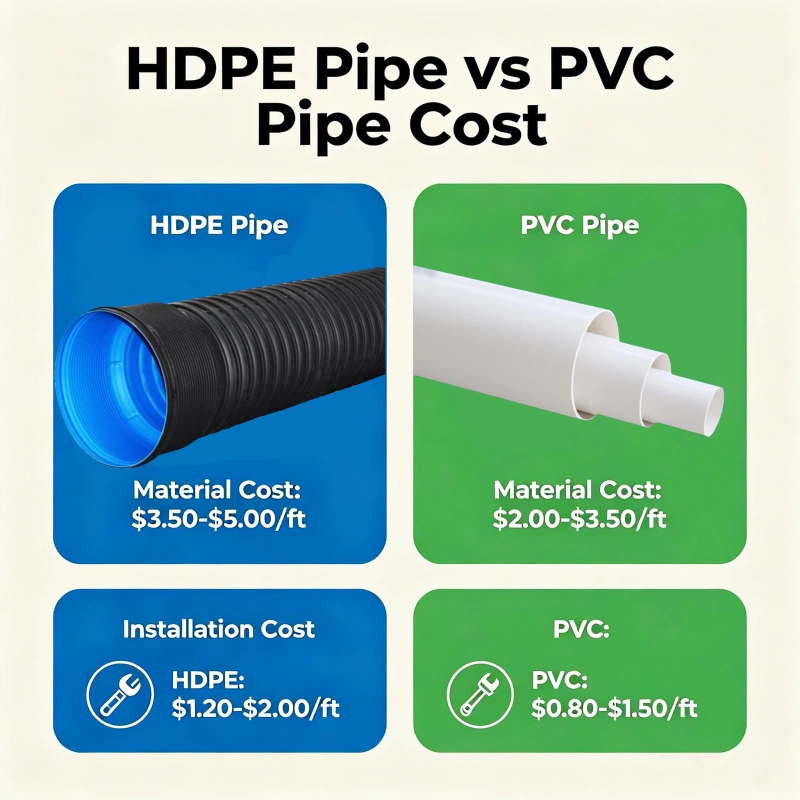
Pipes: The primary conduits, made from materials such as HDPE, PVC, steel, or copper, depending on the application.
Fittings: Elbows, tees, and reducers ensure flexibility and proper alignment of the system.
Valves: Regulate flow, pressure, and direction within the system.
Supports and Anchors: Prevent sagging, maintain alignment, and accommodate thermal expansion.
Design Considerations
Designing an efficient pipe system requires careful planning and adherence to engineering principles:
1. Material Selection: The pipe material must be resistant to the transported medium (e.g., water, oil, or chemicals) and the environmental conditions (e.g., temperature, pressure, and corrosion).
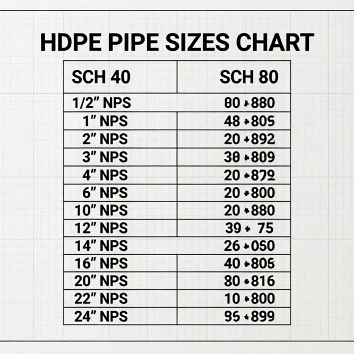
2. Flow Dynamics: Proper pipe sizing and layout are essential to minimize pressure loss and ensure consistent flow.
3. Durability and Safety: The system must withstand operational stresses and external loads, especially in buried or high-pressure applications.
4. Maintenance Access: Incorporating inspection points, valves, and cleanouts ensures the system remains operable and easy to repair.
Challenges and Solutions
Pipe systems face several challenges, including corrosion, leaks, and blockages. Modern innovations, such as the use of corrosion-resistant materials (e.g., HDPE for water pipelines) and advanced monitoring technologies (e.g., smart sensors for leak detection), have greatly improved the reliability and efficiency of pipe systems.

916.webp)
204.webp)
659.webp)
185.webp)
312.webp)
849.webp)
587.webp)
767.webp)